Home >Technology Knowledge

Technology Knowledge

  • 1: What is an FM transmitter?

    Generally speaking, FM transmitter is the abbreviation of FM broadcast transmitter, which is mainly used to wirelessly transmit voice and music programs of FM broadcast stations.


            Any FM radio station, regardless of its scale (national radio station, provincial radio station, municipal radio station, county radio station, township radio station, village radio station, campus radio station, enterprise station radio station, military barracks radio station, etc.), All will be composed of audio broadcast control equipment, audio transmission equipment, FM transmitter and launch antenna feeder.


            A radio station with a large coverage area needs a high-power FM transmitter and a high-gain transmitting antenna to be installed high above the ground; while a radio station with a small coverage area needs an FM transmitter with a small transmission power and an antenna with appropriate gain. And set it up at a suitable height.


    Generally, the power levels of FM transmitters are 1W, 5W, 10W, 30W, 50W, 100W, 300W, 500W, 1000W, 3KW, 5KW, 10KW, etc. Special power FM transmitters can also be customized according to actual needs.


    There are many categories of FM transmitters:


            According to the use occasions of FM transmitters, it can be divided into professional FM transmitters and amateur FM transmitters: professional FM transmitters are mainly used for professional broadcasting stations and occasions that require high sound quality and reliability, while amateur FM transmitters are mainly used for Non-professional radio stations and occasions with general requirements for sound quality and reliability;


            According to the broadcasting method, it can be divided into stereo broadcasting and mono broadcasting;


            According to the circuit principle of FM transmitter, it can be divided into analog FM transmitter and digital FM transmitter: With the rapid development of electronic technology, especially professional FM transmitter, digital FM transmitter is gradually replacing analog FM transmitter. , The distinction between digital and analog is very simple, it depends on whether it uses software radio technology (DSP+DDS or FPGA+DDS) design scheme.


  • 2: How to estimate the coverage distance of FM transmission?

    The coverage distance of an FM broadcast transmission system is mainly related to three factors: 1. The power of the FM transmitter; 2. The erection height of the transmitting antenna; 3. The gain of the transmitting antenna and feeder.


    The power of the FM transmitter can be divided into low power (300W and below), medium power (500W~2KW) and high power (above 3KW). The greater the power, the more beneficial it is to increase the transmission distance.


    The height of the FM transmitting antenna is particularly important for the coverage distance. The higher the height, the better the coverage.


    FM broadcasting transmitting antennas come in various forms, mainly single dipole antennas and double dipole antennas; a complete set of FM broadcasting transmitting antennas are generally composed of single dipole and double dipole basic units. The form of antenna array is composed. The gain of an FM antenna is related to the number of layers of the antenna. Commonly used are single-layer, double-layer, four-layer, six-layer and eight-layer, with gains of 1.5dBd, 4.5dBd, 7.5dBd, 9.1dBd and 10.5dBd respectively. The larger the antenna gain, the better the coverage distance. The transmitting antenna has three modes: vertical polarization, horizontal polarization and circular polarization. At present, most of the polarization modes of vertical polarization are adopted at home and abroad.


    The transmitting feeder will produce loss. Generally speaking, the thicker the feeder, the smaller the loss.


    To estimate the coverage of FM broadcasting, professional software is now available for more accurate calculation and drawing. But the software is expensive; it can also be estimated by manual calculation or by looking up charts.


    It is strongly recommended that the general single launch system can quickly and accurately estimate the coverage distance by looking up the chart. If you need this chart, please follow the official account of this website to obtain the icon for free or add technical support WeChat to obtain it for free, the WeChat account is 138571180.


  • 3: Brief Introduction of AES67 Network Digital Audio Standard

    AES67 network digital audio standard (reproduced)

        AES67 is an open network digital audio standard. It is based on the IP network architecture and adopts the existing IT network protocol to achieve interoperability guidelines for low-latency, high-performance professional audio transmission. Its open protocol and compatibility have greatly promoted the development of digital audio technology based on the IP network architecture.


    1. The background of the AES67 standard

        From the perspective of the development process of radio and television audio systems: from analog audio systems that use many cables, to digital audio systems that introduce the concept of "synchronization", to TDM audio matrix systems, and then to the realization of multiple work rooms based on Ethernet Network interconnection audio system, and then to the network audio technology based on IP architecture to realize remote interconnection (between jobs and between different regions), and now it has formed a multi-site centralized distribution system based on IP architecture. The evolution of audio technology capabilities and the development of IT technology have given the entire audio and video technology industry a ride in IT technology. The audio industry is also facing the arrival of the AolP (Audio over Inter-net Protocol, audio under the Internet Protocol Architecture) era.


        There are currently four network protocols adopted by the Media Networking Alliance (MNA): Livewire, Ravenna, QLAN, and Dante. These four agreements correspond to the four manufacturers in the industry. The Telos represents Livewire, Lawo represents Ravenna, QSC represents QLAN, and Yamaha represents Dante. However, different network protocols are incompatible with each other, which is very troublesome for users. Because most users choose not a certain brand, but a system. There may be many different devices in this system. Some devices use this protocol, and some use that. These devices often cannot communicate with each other.


        Now there is such a set of intercommunication mechanism-AES67, which can connect different protocols together. Currently, the manufacturers covered by the four protocols of Dante, Livewire, Ravenna, and QLAN have reached more than 90%, which means that the AES67 standard can get through 90% of the devices on the market and solve the most difficult problems for users.


    2. The key technology of AES67 standard


    1. Synchronization mechanism

        The receiving end at any place on the network can replay synchronously with other receiving ends through a common clock. The common clock can ensure that all streams are sampled and restored at the same rate, and multiple streams of the same rate can be easily synthesized. The synchronization of the public clock is achieved through the IEEE 1588-2008 Precision Clock Synchronization Protocol. The IEEE 1588 protocol combines software and hardware without requiring additional clock lines. The original Ethernet data lines are still used to transmit clock signals. Networking Simple and efficient.


    2. Media clock

        The digital audio carried on the sending end network is sampled according to the media clock, or its sampling frequency is converted according to the media clock; the receiving end uses it to play digital media streams. The media clock has a fixed relationship with the network clock. The media clock is compared with the network clock. To have a more precise rate, the rate should be consistent with the audio sampling frequency. This standard supports three sampling frequencies: 44.1KHz, 48KHz, 96KHz.


    3. Coding

        Encoding is a method of digitizing audio signals into a sequence of data packets that can be streamed. The format of the payload defines the encoding of audio samples. The AES67 standard supports payload formats including L16 and L24. L16 is an encoding format for uncompressed audio data collection, and L24 is an extension of L16. The 16-bit or 24-bit uncompressed audio data sample value is represented by sign-shaped two's complement. Among them, the range of L16 is -32768 to 32767.


    4. Transmission

        Transmission defines the operation of the encoded and packaged media data on the network layer and the transport layer. In this standard, media data packets at the network layer should be transmitted based on IPV4; the transport layer should use real-time transport protocol (RTP) to transmit audio data information, use real-time transmission control protocol (RTCP) to transmit control information, and equipment should use UDP protocol To transmit RTP packets.


    The real-time transmission protocol provides end-to-end transmission services with real-time characteristics for data, with the purpose of providing time information and realizing stream synchronization. The real-time transmission control protocol is responsible for managing transmission quality, exchanging control information between current application processes, and providing flow control and congestion control services.


  • 4: What is the STL system in the broadcasting and television ?

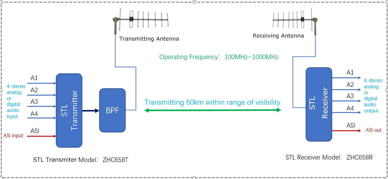
    The digital STL audio and video transmission system is a professional system which can transmit 4 stereo (or 8 mono) analog/digital audio signals and 1 digital video signal wirelessly from the studio to the transmitting station. The system uses state-of-the-art software-defined radio (SDR) technology, digital code modulation, digital demodulation and decoding to transmit and receive, enabling audio/video signals to be transmitted at very high quality and with virtually no damage.


    One set of standard configuration STL system equipment has a transmission distance of 60 kilometers in line of sight. The transmission system consists of STL transmitter, transmission filter, transmitting antenna & feeder cables, receiving antenna & feeder cables and STL receiver.


    The diagram as below:

    STL.png

  • 5: Professional digital audio interface—AES/EBU

    AES is the Audio Engineering Society of the United States, and EBU is the European Broadcast Union. AES/EBU refers to a professional digital audio interface standard, which is now a more popular professional digital audio standard.


    This standard was specially formulated for professional use. It was promulgated in 1985 (AES3-1985) and revised in 1992 (AES3-1992). It has been widely supported by international authoritative professional organizations.


    AES/EBU is an uncompressed digital audio format that uses one-way serial code to transmit two channels of high-quality digital audio data (up to 24 bit quantization); it also transmits related control information (including the source of the digital channel). And the destination address, date and time code, number of sampling points, byte length and other additional information) and has the ability to detect error codes.


    The AES/EBU channel is self-synchronizing, and the clock information comes from the sender and is expressed by the AES/EBU digital stream. Its three standard sampling rates are 32KHz, 44.1KHz and 48KHz.


    AES/EBU is based on a single twisted pair as the physical connection medium, adopts a balanced transmission method, the standard impedance is 110Ω, and uses XLR (XLR) plug-ins; it can transmit data over a distance of up to 100 meters without equalization; if Balanced, can transmit up to 1000 meters; use optical fiber to transmit to longer distances.


  • 6: How to achieve FM broadcast coverage in the tunnel?

    We have all had this experience: when we were listening to a radio program of interest, the vehicle entered the tunnel and immediately could not listen to the radio normally; when the vehicle left the tunnel, it was a pity that the radio content had passed.


    In order to solve the problem of uninterrupted listening to radio programs in the tunnel, the "tunnel broadcast coverage system" came into being. The system can introduce all radio programs outside the tunnel into the tunnel with high fidelity for seamless coverage, so that the audience can listen to radio programs uninterrupted. Moreover, when an accident in the tunnel causes traffic congestion, emergency information to guide traffic can also be broadcast through broadcast programs of all frequencies.


    A complete tunnel broadcast coverage system consists of a receiving antenna outside the tunnel, a near-end unit, a remote unit, a leaky cable or transmitting antenna, an emergency broadcast processor, and so on. For details, please click Tunnel Broadcast Coverage System for details.


    The same technology and products can also be used in closed occasions such as underground parking lots.


    Hangzhou Zhongchuan Digital Equipment Co., Ltd. has implemented broadcast coverage projects for nearly 100 tunnels in China, and the coverage effect is perfect. The equipment is stable, reliable and cost-effective.


  • 7: What are the main technical parameters of the FM broadcast transmitter?

    The technical parameters of the FM broadcast transmitter are divided into radio frequency parameters and audio parameters:


    Radio frequency parameters include: transmit power and deviation, transmit frequency and deviation, residual wave radiation, etc.;


    Audio parameters include: signal-to-noise ratio, distortion, frequency response, stereo separation, etc.


    Relevant national standards and industry standards specify the size of various parameters.


  • 8: How to calculate the fiber link loss?

    Optical fiber link loss generally consists of optical fiber distribution loss, optical cable attenuation loss, optical fiber connector loss, and so on.


    Optical fiber distribution loss: It is the loss that occurs after the optical signal passes through the optical splitter, which is composed of distribution loss and additional loss. For example: 3.9dB for 2 splitting and 7.4dB for 4 splitting.


    Optical cable attenuation loss: It is the loss of optical signal after long-distance transmission of optical cable, which is related to the length of optical cable and optical wavelength. For example: 1310nm is 0.4dB per kilometer; 1550nm is 0.25dB per kilometer.


    Optical fiber connector loss: it is the loss of movable optical fiber connector products, and the loss caused by different types of connectors is also different. In terms of engineering, in order to simplify the calculation, the insertion loss of each connector is 0.5dB.


message